Double buffer technique is effect to execute tasks in pipeline fashion for higher throughput, which is also known as ping-pong buffer. In this blog, I’ll discuss the implementation of double buffer in HLS, based on which I’ll deploy a simple example on ZCU102 board.
###High Level Overview
We use the instance in paper titled Optimizing FPGA-based Accelerator Design for Deep Convolutional Neural Networks as an example to show how to implement a double buffer design in HLS.
The schedule graph of the whole system is shown as follows.
As we can see from the above graph, there are three tasks: (1) load input buffer, denoted as LB, (2) computation COM, (3) store output buffer SB.
In this example, the latency of SB is much larger than other two tasks. Specifically, it is roughly four times larger than COM. Therefore, for one iteration of SB, tasks COM and LB will be executed 4 times.
The above sequences will be controlled in PS part.
In the following, we will first discuss the design of PL part. Then, we discuss the control logic later in this blog.
###The Design of PL part
In PL part, we design two IP cores: one for LB and COM, and the other one for SB , because the following two reasons:
- LB and COM are alternatively executed
- one execution of SB and 4 executions of LB and COM are overlapped
#####IP core (dma_test) for LB (read_data) and COM (fire)
This IP contains two functions: “read_data” and “fire”, where “read_data” will receive data from DDR in PS part through DMA, and “fire” will process the received data. In this example, we perform some dummy operations in fire. For a specific scenario, the fire can be the function of conducting convolution etc.
As we can see from the schedule graph, when “fire” operates buffer 0, “read_data” function will fill buffer 1. Hence, we allocate two buffers to hold the input data.
For the output of “fire” function, we directly write the results to the next IP through AXI_STREAM.
The detailed codes in the top level function are listed as follows.
|
|
As we can see, we allocate two buffers IFM_0 and IFM_1 to hold the input data.
In each if-else block, “read_data” and “fire” operate different buffers. In consequence, these functions will be implemented in parallel automatically by HLS.
The “read_data” function is listed as follows.
|
|
Finally, the “fire” function is listed as follows.
#####IP (dma_sending) core for SB (dma_sending)
This IP contains two functions: “read_from_fire” and “write_data”, where “read_from_fire” will receive data from “fire” defined in the first IP core, and “write_data” will send data to DDR in PS part through DMA.
As we can see from the schedule graph, when we write data to PS’s DDR, the newly computed data need to be write to this IP core. This means “read_from_fire” and “write_data” need to be executed in parallel. Therefore, we allocate two buffers OFM_0 and OFM_1 to apply double buffer to execute these functions in parallel.
The detailed codes are listed as follows.
|
|
As we can see from the above codes, in each block, “read_from_fire” and “write_data” operate different buffers. In consequence, these functions will be implemented in parallel automatically by HLS.
The “read_from_fire” is implemented as follows.
|
|
And the “write_data” is shown as follows.
###The Block Diagram for the Connection of IPs
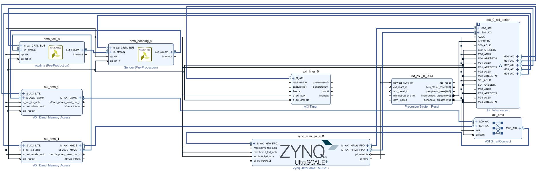
According to the design of PL part, the input port of ip core dma_test is connected ZYNQ through axi_dma_1 and hp0. The output port of dma_test is directly connected to the input port of dma_sending.
And the output port of dma_sending is connected back to ZYNQ through axi_dma_0 and hp_0.
###The Design of PS part
In our design, LB and COM will execute 10 times for one execution of SB.
And we assume the SB will be executed 10240 iterations.
We can notice that in each ip core, the variable num will decide the alternatively using of buffers. Hence, we will increase num by 1 in each iteration.
To realize the ping-pong executions, in each iteration, we first launch SB and then launch LB and COM in a inner-loop with 10 iterations.
The detailed codes are shown in as follows.
|
|
###Performance Results
Results in HLS
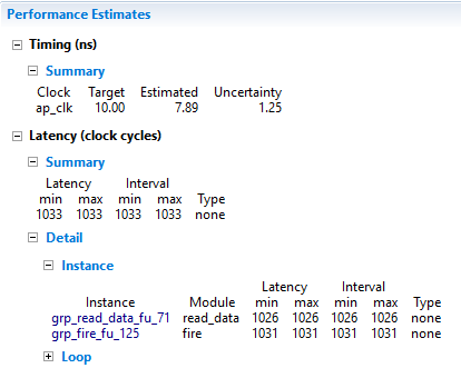
The results of IP core 1 is shown in the following figure.
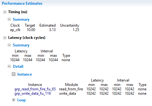
The results of IP core 2 is shown in the following figure.
Results on ZCU102
The results are listed as follows.
Inspiration
For each iteration, we send 1024104B=40KB from PS to PL. And send 102404B=40KB data from PL to PS. In total, data transmission size is 80KB10240=800MB.
So, the bandwidth is 800MB/1.389253=575.85MB/s (two channels). For one channel, the bandwidth is 287.92MB/s.
This is mainly bounded by the PL part. More specifically, the clock in PL part is 100MHz. In each clock cycle, it can write/read 4B data to/from BRAM. Hence, the bottleneck in PL part is 4/1.0E-8/1024/1024=381.46MB/s.
The paper titled Bandwidth Optimization Through On-Chip Memory Restructuring for HLS discussed the bandwidth optimizations. In the next blog, I’ll talk about the bandwidth optimization for HLS design.
BTW, this paper also introduce the double buffer, which is the same as we discussed above.
